This tutorial was written on Windows 10 using WSL with an O3DE version that
was built from source, on commit e2c4c0e5e3
In the previous article we wrote Lua scripts to control our start menu.
In this article we are going to create the assets that we can use to make our pong game.
Ground Material
First let's change the ground material so it's not the default grid. Expand the Atom Default Environment
entity in the Entity Outliner and select the Ground entity.

With it selected, look for the Material component on this entity.

If like this image, your options are greyed out you will need to press the
Generate/Manage Source Materials... button. This will open up a Generate/Manage Source Materials...
dialog, where you can set the name for the new material.
 |
 |
| Notice how our options are no longer greyed out as we have our own material instance now. |
I believe what is happening here is by default the Ground object is using a
shared material. If you want to make changes to it, you need to create a new
instance of the material that isn't shared with other objects. This button
creates a new material, copying over the default settings, so you can modify
it for this object.
Now we can click the Edit Material Instance button which will open our Material Property Inspector
 |
 |
The Material Property Inspector is a condensed version of O3DE's Material Editor, both of which
allow artists to view and edit PBR materials. In the Material Property Inspector we can set various
textures, for example, that will control how this material is rendered. Things like
Color, Metallic, and Roughness images (sometimes referred to as Maps)
each add properties to the material that is used by the renderer to affect how
it looks.
For more information check out the official documentation
In the Material Property Inspector locate the BaseColor section and find
the property for texture. This is the property that is references the
grey checkerboard pattern. Click on the X button next to this path which
will remove the texture. The ground of your level should now be a headache
inducing flashbang color.
 |
 |
Lets fix this by clicking on the box next to the Color property of the Base Color
section. This will open up a dialog where we can input new color settings. Let's
choose a neutral blue/grey color like Red 67,Green 106, and Blue 146. Now
looking at our level won't cause migranes.
 |
 |

After we are happy with how our material looks, make sure to save your changes
by using the three bar dropdown in the upper right of the dialog, and selecting
Save Material. Save it into your project, we choose to create a Materials
folder to put it in, and name it Ground.material
 |
 |

Editor Only Grid
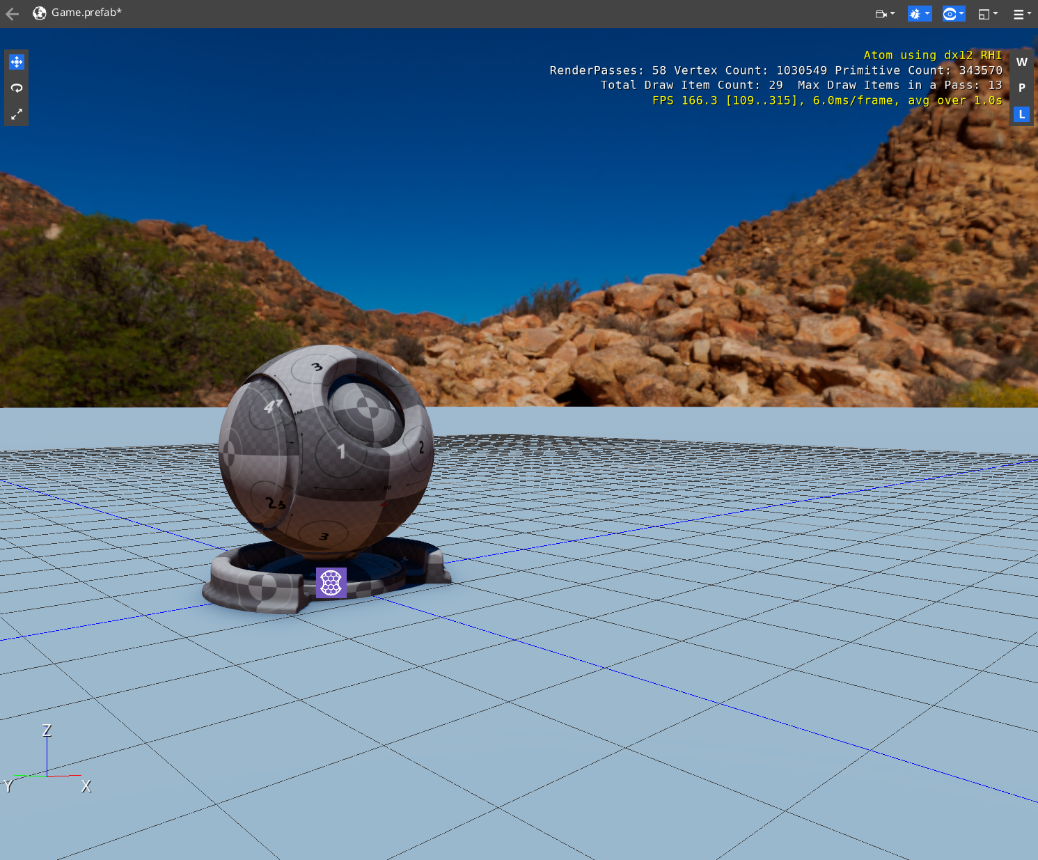
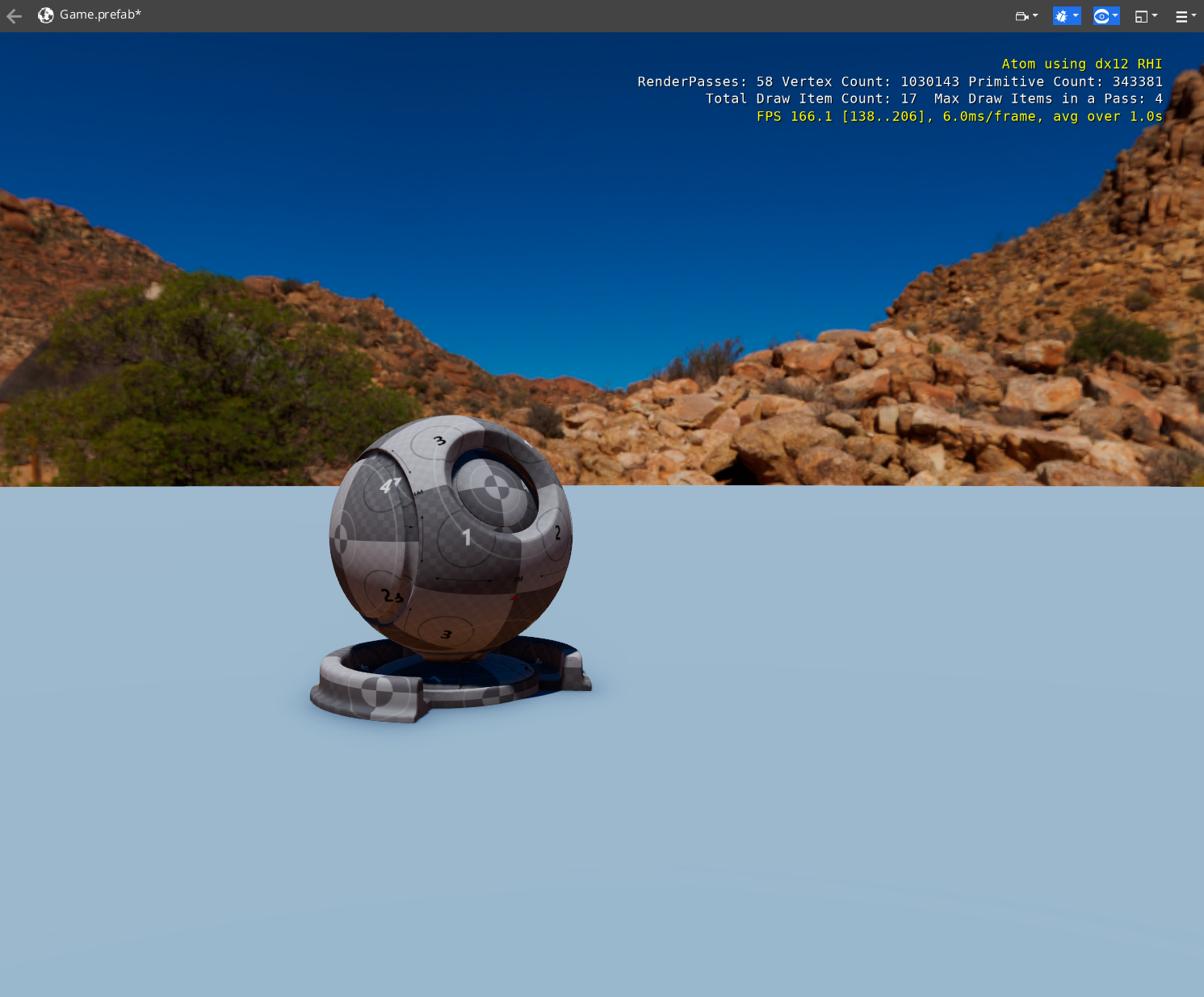
The Grid component is a useful tool for helping to layout objects, but
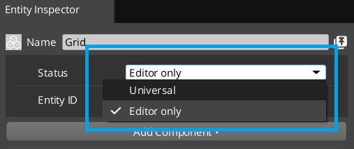
we don't want it displaying during gameplay and obstructing our view. Let's set
it to be an Editor Only component so we can see it in the editor, but
not while we are playing. Find the Grid entity under the Atom Default Environment
entity and select it in the Entity Outliner. Over in the Entity Inspector
change the status from Universal to Editor Only.
 |
 |
 |
 |
| Editor Mode | Play Mode |
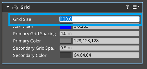
While we are here, lets also make the grid larger. We'll need more space for
our pong playing area. On the Grid component, change the Grid Size property
to 100.
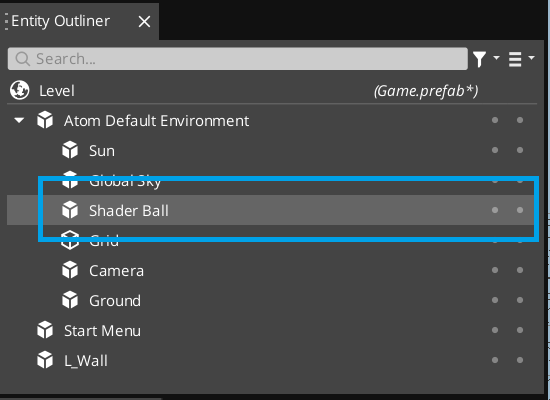
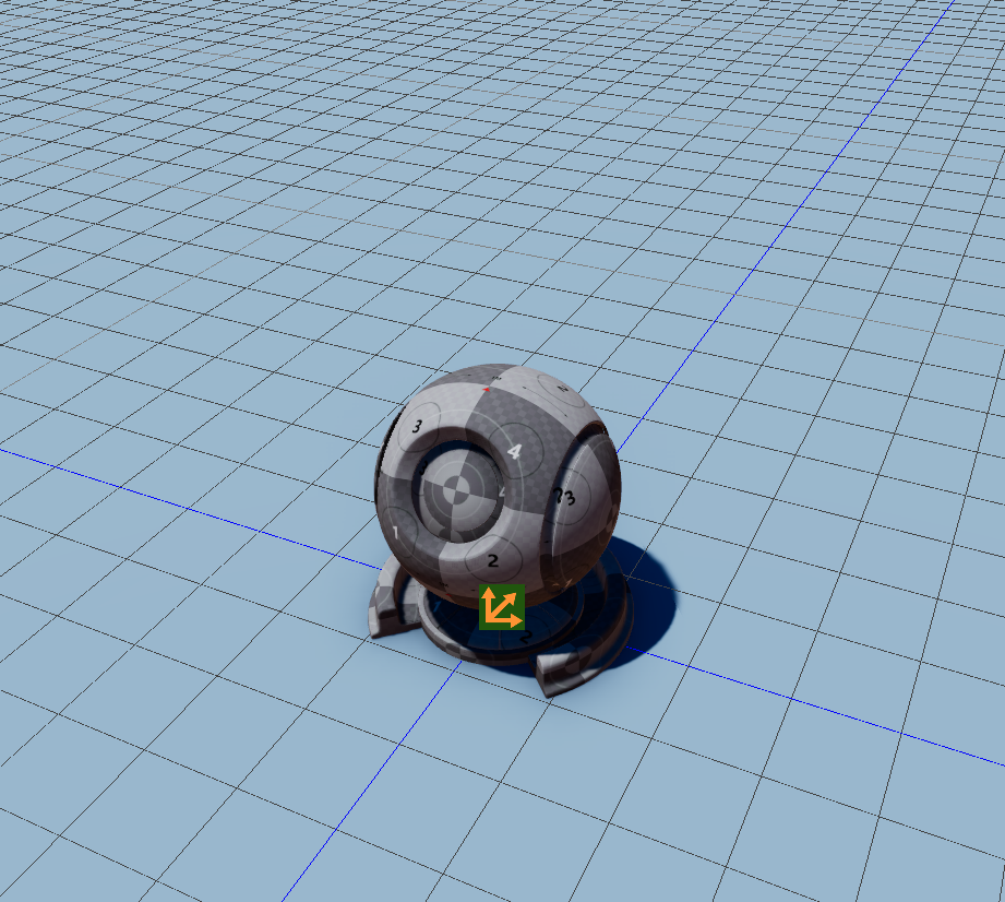
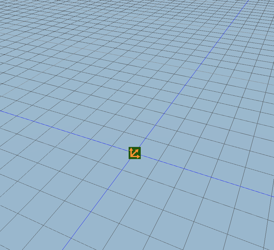
Remove the Shader Ball
By default, the level comes with a Shader Ball object added. We should
locate it in the Entity Outliner under the Atom Default Environment entity.
Select it, then press the Delete key to remove it from your scene.
 |
 |
Adding White Box Gem
The White Box gem is a gem containing components and utilities to help rapidly
create geometry for prototyping and experimentation. We will be using it to create
the geometry for our game.
If you created your project with the default gem configuration, you should
have the White Box gem added already. You can skip ahead to the Create The Walls section. If you need to add this gem, you can do so now.
First you'll need to close your editor, and go back to the O3DE Launcher.
Using the three bar dropdown for your project,
select Configure Gems...
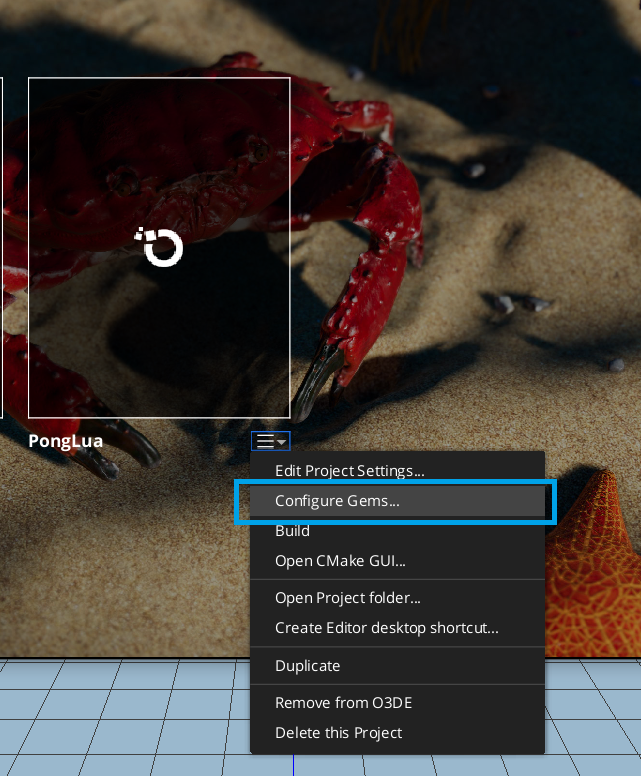
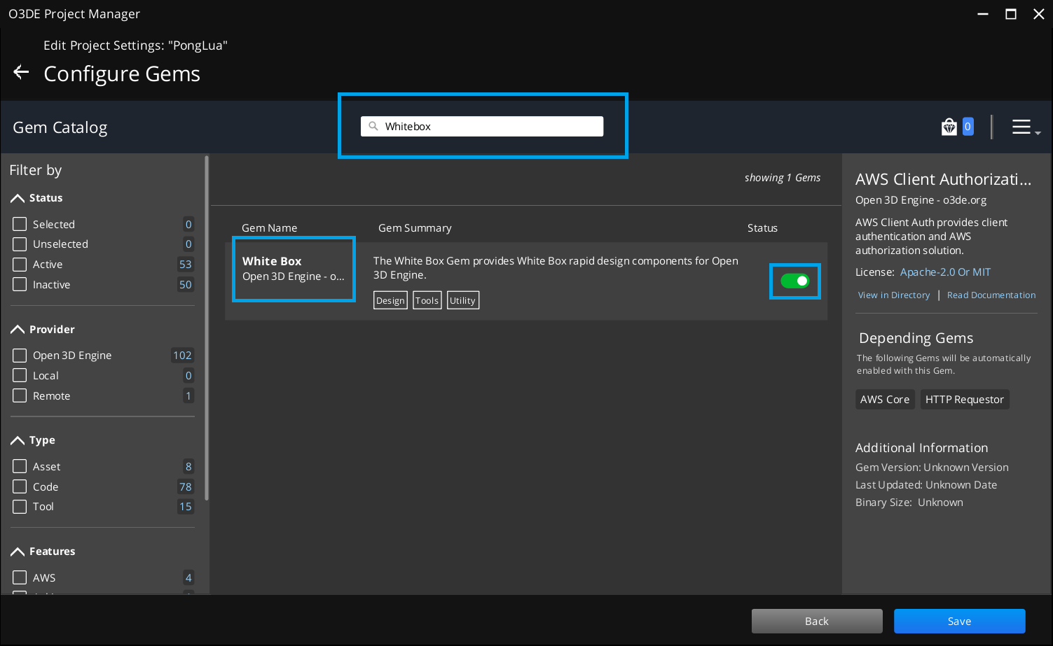
Then from the Configure Gems window, use the search bar to locate
the White Box gem, and ensure the toggle is enabled. This
will require you to rebuild your project.
Create The Walls
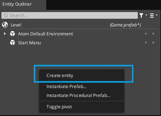
Right click the Entity Outliner and select Create Entity from the dropdown.
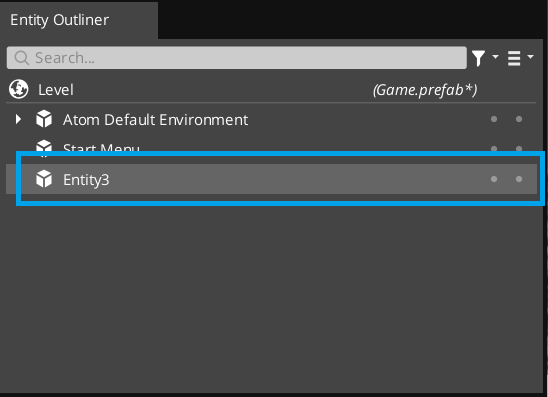
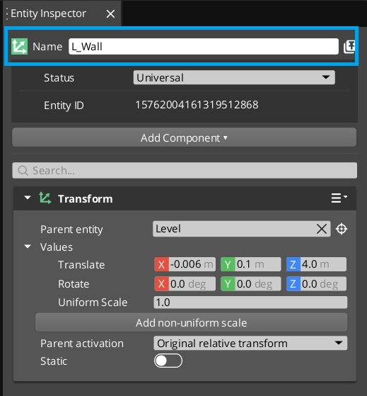
Select it in the Entity Outliner and rename it to L_Wall.
 |
 |
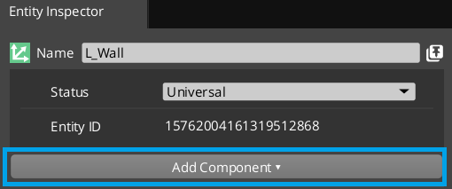
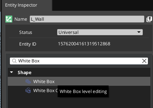
Next we are going to add a White Box component to our L_Wall entity. Use
the Add Component dropdown and search for White Box. Add this component and
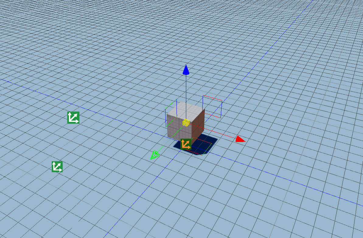
you should have a cube added to your scene.
 |
 |
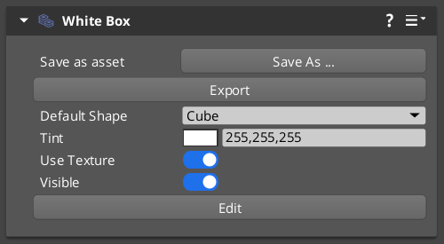 |
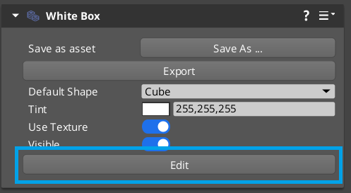
In the White Box component, we can press the Edit button to go into Edit Mode.
This will allow us to grow and shrink the cube by grabbing its faces, edges, and
vertices.
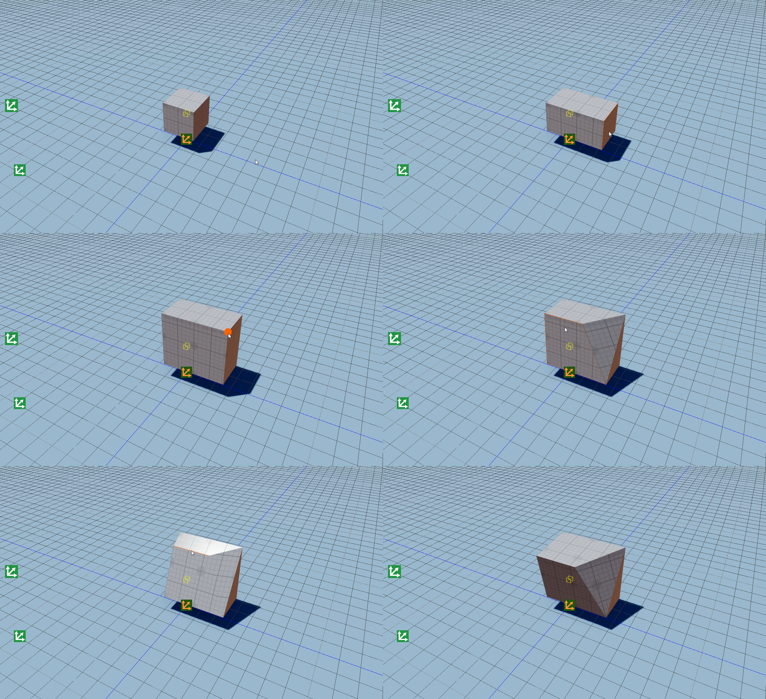
You can press Ctrl+Z to undo any changes you make, and when you are finished you can press
the Done button to set your changes.
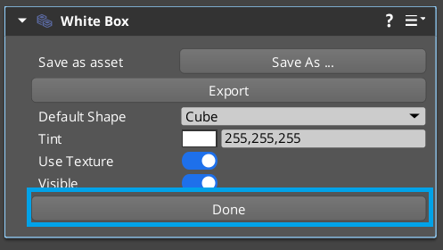
Note that while you are editing a White Box component, most of the Editor UI
is greyed out. You must finish editing and press the Done button to exit edit mode.
There are a lot more cool things you can do with the White Box component
that we won't cover here. Check out this Lumberyard Tutorial
that looks at some of the more advanced things you can do with a White Box.
 |
 |
Enable Snap to Grid
This is very handy, but it's hard to control and be exact. For that, we should
enable Snap to Grid which allows us to snap to discrete sizes, so we can be
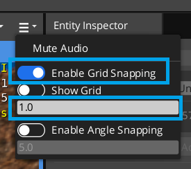
a little more exact with our White Box. To enable snap to grid, use the three
bar dropdown on the top right corner of the Level View, and activate the Snap to Grid
toggle. Also, there is a field that allows you to control the increments to snap to.
By default it is set to 0.1, change it to 1.0.
 |
 |
Building the Walls
Now lets use the white box tool to build our left wall.
It doesn't have to be exactly like this, we can always edit it later.
Once you are happy with the shape of your wall, press the Done button in the
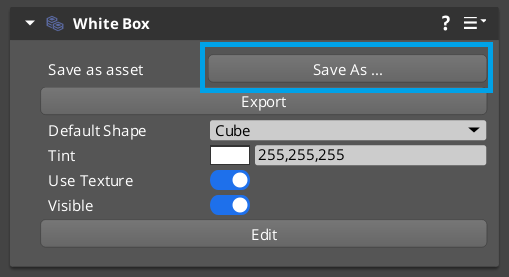
White Box component. Then lets save this White Box as a component. On the
component, press the Save As button, then save the asset to your project. We
chose to put it in a folder called Meshes and name it Side_Wall.wbm.
As you might be able to guess based on the name Side_Wall we can create another
wall, the R_Wall by duplicating our L_Wall and moving it to the other side
of the play space.
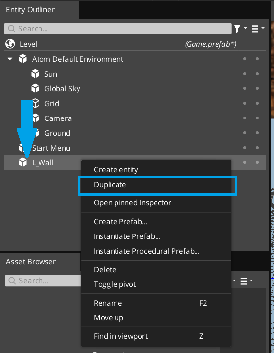
Right click L_Wall and select Duplicate from the popup window. Rename
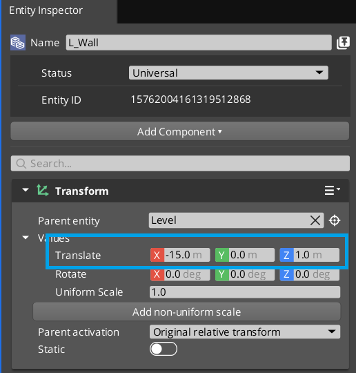
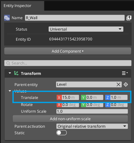
this new entity R_Wall. Using the Transform component, set the translate property
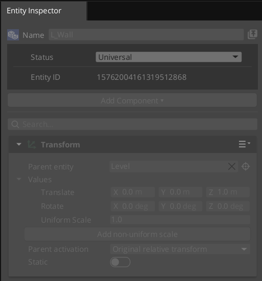
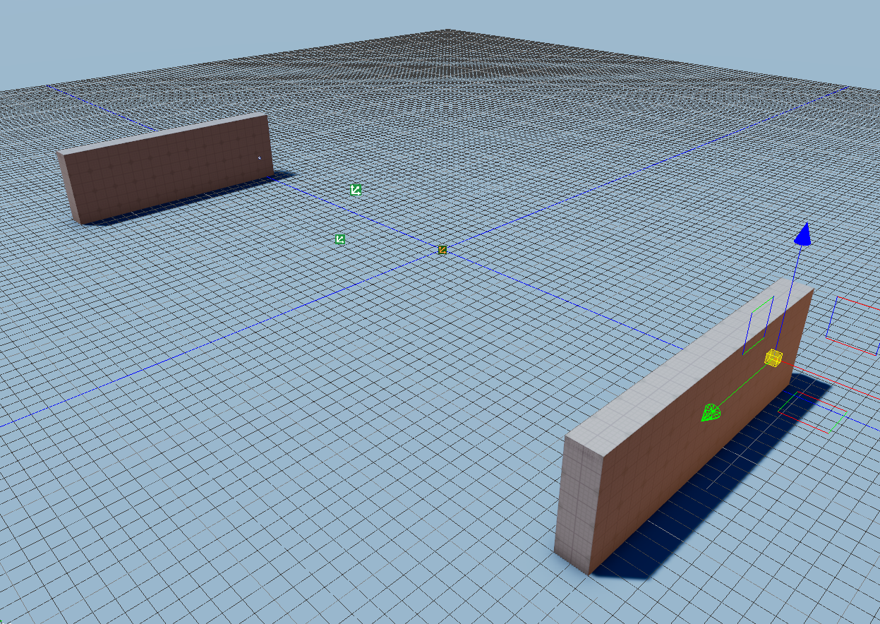
of L_Wall to -15, 0, 1.0, and the translate property of R_Wall to 15, 0, 1.0.
This will put them about 30 units apart. Again, we don't need to be specific, we
will be adjusting these in the future as we build up the game more.
 |
 |
Completing the Arena
We can repeat these steps to build our top and bottom walls.
You can full screen this video to see better.
We made this a little narrow, lets edit it to make it less rectangular. Since we are reusing the same assets for the left and right walls, we only have to edit one, and it will change them both!
By reusing the side assets it's easy to make changes.
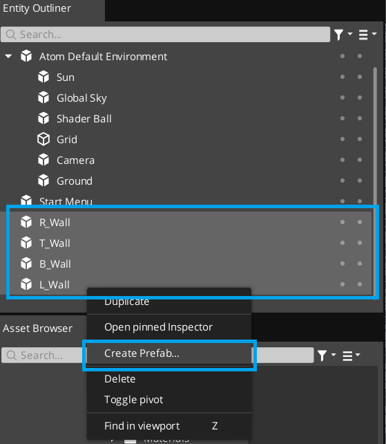
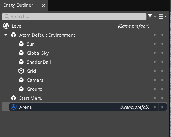
Once we have the arena in the shape we like, lets create a prefab to bundle
them together. Select all the Walls in the Entity Outliner and from the
right click popup menu select Create Prefab. Save the new prefab to your
prefabs folder called Arena.prefab.
 |
 |
A Note About Prefabs
There's actually not a lot of information about prefabs in O3DE.
is empty as of the writing of this post.A similar concept of
sliceswas in LumberyardHowever in a Developer Blog
made last April, they talked about creating a new system called `Prefabs`
for Lumberyard.
It's unclear to me which system we have in O3DE, but based on the Slices
screenshots and the fact that all the UI says `Prefab` I'm assuming
  we are using the new as of yet undocumented system described in the blog?
It's possible that I am misusing it here, since we don't plan on actually creating multiple instances of this Arena. It might be overkill to use a prefab just as a means of grouping a set of Entities. Based on the slice documentation, this instantiatess an entity to act as the root transform anyway, so maybe just nesting them under a single Entity is the best way to handle this grouping.
Either way I wanted to create a prefab and play with them anyway, and the blog made a big deal about them being intuitive to use. Lets test that assertion!
Centering the Arena
The way I created the arena has it slighly off center. So lets reposition the
walls so the center of it is the origin of the level [0,0,0] while the arena's
position is at the origin.
To begin editing the prefab I double clicked it.
After moving the parts around I saved by pressing Ctrl+S which tried to save
the scene while I was editing the prefab. A dialog popped up asking if I wanted
to apply the changes to the scene object to the original prefab. I said yes.
Then I clicked (what I think is) the stop editing prefab button.
You'll notice I put the shader ball back in so I could see where the world origin was.

What I think is the Stop Editing Prefab button.
We have completed building the arena!
Positioning the Game Camera
Next, lets get the game camera into a good position for the game. To do this,
we are going to use. Since we positioned the arena exactly around the origin
of the level, we can make a rough guess as to what the camera position and orientation
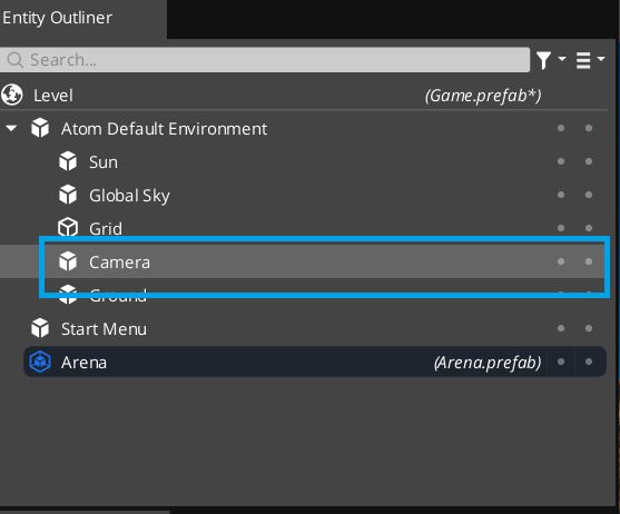
should be. Click on the Camera entity (again, a child of the Atom Default Environment
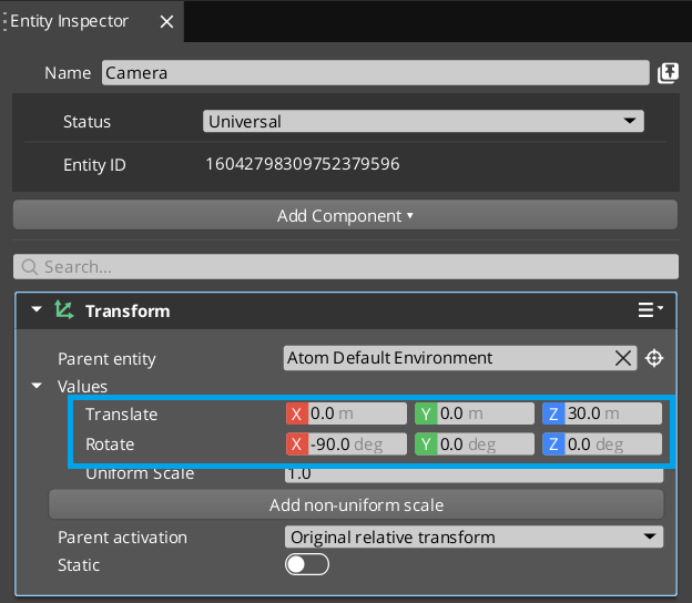
and type the following values into it's Transform component.
First position the camera directly over the origin, above the ground by 30 units.
So the position should be [0,0,30]
Next set the rotation to be facing downwards, [-90,0,0]
 |
 |
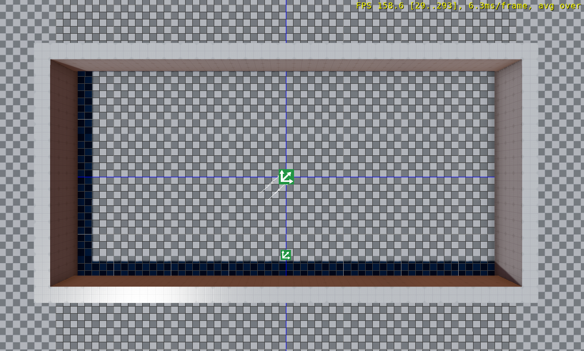
This is a reasonable guess, but how do we know how it looks? We can play the
game, and that will show us, but what if we wanted to position a camera that wasn't
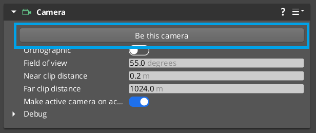
on by default? There is a better way. With the main camera still selected
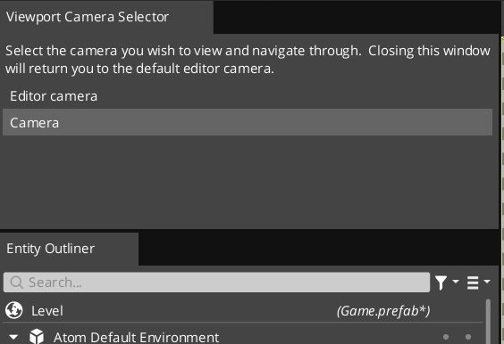
under the camera button select the Be This Camera button. You will now see
the world through that cameras perspective. It will also open a new window called
the Viewport Camera Selector window. This will allow the viewport to be seen
from multiple different cameras, and let you easily switch between them.
 |
 |
Delete Fly Camera
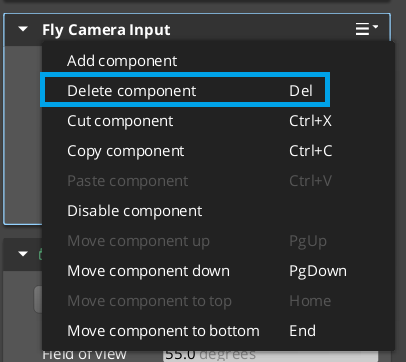
Lastly, lets go ahead and remove the FlyCameraInput component from the camera,
since we no longer want the player to move it around when we run the game. Right
click the component in the Entity Inspector and select Delete Component
Now that the fly camera is gone, we are going to need to update our StartMenu.lua
file so that it no longer tries to enable it when we start the game. Delete the
EntityId reference in the Properties area, as well as removing the lines
27 and 28 which send an event to the FlyCameraInputBus.
 1
 2 --
 3 -- Properties #################################################################
 4 --
 5 StartMenu = {
 6     Properties = {
 7         cameraId = EntityId()
 8     }
 9 }
10
11 --
12 -- Input Handler ##############################################################
13 --
14
15 -- there are 3 handlers we can receive for each input: OnPressed, OnHeld, and OnReleased
16 -- they each come with a value that may represent the state of the input (for example
17 -- the tilt of a thumbstick).  This is configured in the input binding.
18 function StartMenu:OnPressed (value)
19
20     -- get the canvas id from the UI Canvas Ref component on our entity
21     local canvasId = UiCanvasRefBus.Event.GetCanvas(self.entityId);
22
23     -- send a message to the Ui Canvas with the id we got from the Ui Canvas ref
24     -- and tell it to disable itself
25     UiCanvasBus.Event.SetEnabled(canvasId, false);
26
27     -- tell the fly camera input component on the camera to enable.
28     FlyCameraInputBus.Event.SetIsEnabled(self.Properties.cameraId, true);
29 end
30
31 --
32 -- Lifecycle ##################################################################
33 --
34
35 function StartMenu:OnActivate()
36     -- connect to InputEventNotificationBus and set ourselves as the handler
37     self.InputNotificationBus = InputEventNotificationBus.Connect(
38         self, InputEventNotificationId("EnterToStart")
39     );
40 end
41
42 --
43 -- ----------------------------------------------------------------------------
44 --
45
46 function StartMenu:OnDeactivate()
47     self.InputNotificationBus:Disconnect();
48 end
49
50 --
51 -- ############################################################################
52 --
53
54 return StartMenu;
Making the Paddles
We will be using a similar process to creating the paddles that we did for
the walls. Create an entity by right clicking in the Entity Outliner and selecting
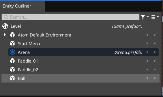
Create Entity. Name the new entity Paddle_01. Add a White Box component
to it and use that component to shape the paddle to the desired dimensions. You
may need to adjust the snap to configuration to get the desired shape.
Once we have finished creating the paddle, click Done on the White Box component,
then use the Save Asset As to save the paddle mesh as Paddle.wbm in the meshes
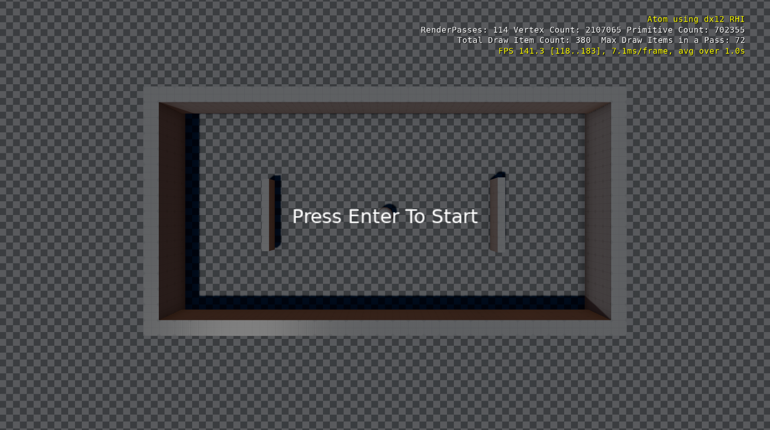
folder. Position Paddle_01 at -8.0 on the x-axis.
Duplicate Paddle_01 and name it Paddle_02. Position it at 8.0 on the x-axis.
You can see this is not rehearsed!
Making the Ball
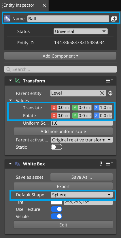
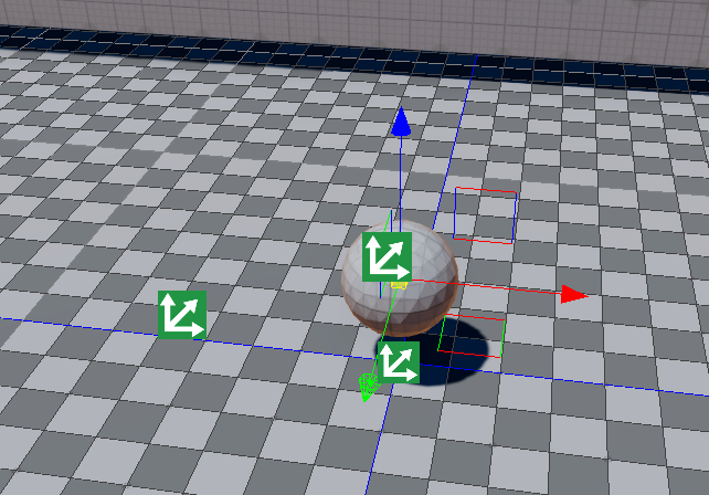
Again we will be creating an entity and adding a White Box component to it,
but this time we want to set the Default Shape of the White Box component
to Sphere instead of Cube. We also want to position this at the center
of the level, with a z value of 1.
 |
 |
Fixing Errors
If you've noticed in your console there have been some errors telling you
[Error] (Prefab) - Invalid asset found referenced in scene while entering game mode
It appears as if this is caused by not saving your White Box assets. Make sure
you save the Ball.wbm, Paddle.wbm and both types of walls and the error goes away.
Remember the T_Wall and the B_Wall can share the same mesh, as well as the paddles,
and the L_Wall and R_Wall.
Conclusion
Make sure to save your work with Ctrl+S or File | Save
In this guide we covered a lot of new topics, including:
- Editing materials.
- Working with the
White Boxcomponent. - Playing around with
Prefabs - Working with grid snapping.
In the next article we are going to learn how to script paddle movement.
